As a very basic definition of home automation is able to be controlled in your home. If you have a remote or you have automatic control over the function within your home, you have home automation. Today’s standards are high. There are actually a number of different ways that you can install this type of automation into your home. What’s important to know is that most of the automation that you will do will not require hard work. It won’t require tearing apart your home or spending thousands of dollars on a simple system. Home automation is something that the average person can do. Most of the products that you will find are simple to install and they don’t have to be more than a few hours worth of a project.
Home automation can allow you, and your computer, to make the things that you need and do in your home easier to accomplish. Perhaps you want to control your security system? Or, perhaps you want to voice automate the lights in your home so that you can get into bed and then turn the lights out. Or, perhaps you want to be able to control your sound system from anyplace in your home. No matter what it is you are looking to accomplish, home automation products are probably available to help you to make it happen. A typical home automation system allows one to control house hold appliances from a centralized control unit. These appliances include lights, fans, air conditioners, television sets, security cameras, electronic doors, computer systems, audio/visual equipment, etc. These appliances usually have to be specially designed to be compatible with each other and with the control unit for most commercially available home automation systems.
The project Smart Home Automation, demonstrates a system that can be integrated into a home/building’s electrical system and allows one to wirelessly control lights, fans, and turn on or off any appliance that is plugged into a wall outlet. The system can be controlled from a Bluetooth or Wi-Fi enabled device such as a mobile phone or laptop, while a microcontroller powered box act as the server. Thus the installation cost and hardware cost is kept to a minimum as most users already own the requisite hardware such as a mobile phone and desktop PC.
A Bluetooth dongle or a standard Wireless Access Point is used to provide connectivity between the server and the mobile device. The system is capable of detecting when the user enters or leaves the room by measuring the change in environmental thermal equilibrium, and can accordingly turn on or off appliances such as lights and fans. The power supply for each appliance is wired through an electromechanical relay. A number of relays are used depending on the number of appliances to be controlled. All the relays are controlled by a microcontroller. The microcontroller based host acts as the mmain server.. The server can also receive connections over the internet and can be controlled from a remote location. This opens up many possibilities. For example, one could remotely turn on the air conditioner from the office before leaving so that the room is cool before reaching home. Home automation can range in complexity from the simple gadgets and gizmos that provide control over individual components to individual home sub-systems and integrated whole house systems.

Figure 1.1 Wall control panel for smarthome
The metaphor of a tree with branches reaching into different locations is a good image for an integrated full home automation system. Each branch of the tree performs a different function. One branch of the tree might include home entertainment, such as television and audio. A second branch could include security, including video surveillance. A third branch could include telecommunications, like telephone and intercoms and a fourth branch could include energy and environmental management including air and water quality, lighting and thermal-comfort. An essential ingredient of home automation is system feedback. Feedback brings intelligence to automation. It is important to note that home automation systems are quite diverse and many configurations are possible. The four branches described above could, in fact, be replaced with eight branches or two branches. Often the branches have interconnections. For example, a home entertainment system and the security system might utilize the same video monitor. Some home automation systems are packaged as fully integrated systems whereas others provide only a limited set of functions. Standard integrated packages usually include security systems, HVAC control, lighting and appliance control. Interface panels and remote access capabilities are essential components of integrated systems and some individual subsystems as well. Both wireless and hard-wired systems are available.

Figure 1.2 Basic scheme of smarthome integration
Some common devices used in home automation systems are:
- burglar alarms
- video entry systems
- programmed thermostats with zoned heating
- and cooling
- intercoms
- entertainment systems with many speaker
- and video connections
- central vacuums
- hazardous gas detectors
- electronic air cleaners
- water filtration systems
- flood alarms.
As implied above, there are different levels of home automation. While the more advanced systems are comprehensive, many households elect not to have a complicated system because they only desire control over one or two functions. The standard security alarm system, in fact, can be viewed as an example of home automation at a low level. The difference between low level and high level systems are based on the extent of control provided, the degree of feedback, the level of “intelligence” and the sophistication of the user interface. For example, although a standard security system with central station monitoring has a fairly high level of technology, most such systems have to be set manually as occupants leave and de-activated manually as occupants enter the home. More sophisticated systems include a remote transmitter, similar to those used for remote control of automobile alarm systems, that can be activated as an individual arrives home or as one leaves. Higher level systems could also include several pre-programmed modes, based on the day of the week and the time. The user would not have to key in the appropriate modes when leaving or entering; the system would automatically set itself based on pre-established criteria. As another example, sensors to detect heating system or sump pump failures can activate alarms, but a more sophisticated system could notify the occupant at work, if they’re not at home. The more intelligent system might also automatically activate a back-up sump pump if the main pump failed. While many “occupancy sensors” exist to turn on and off lights and appliances as individuals move through a house, higher level controls can adjust to individual preferences. For example, Bill Gates’ widely publicized new home has a system that adjusts the lighting, multimedia displays and other features automatically to individual user preferences. Prospective guests to the home will be given a questionnaire and data will be entered into the home computer about their preferences. Guests and residents will wear “badges” that transmit coded signals notifying the home computer of their whereabouts. The computer program will adjust the environment to the individuals preferences as they use specific parts of the home.
1.1 What can home automation do?
Home automation can:
- Increase your independence and give you greater control of your home environment.
- Make it easier to communicate with your family.
- Save you time and effort.
- Improve your personal safety.
- Reduce your heating and cooling costs.
- Increase your home’s energy efficiency.
- Alert you audibly and visually to emergency situations.
- Allow you to monitor your home while you are away.
1.2 OBJECTIVE OF THE PROPSED SYSTEM
The objective of the proposed system is to offer a low-cost solution for a home automation system that overcomes the above drawbacks. The system provides basic control of appliances at a fraction of the cost of commercially available systems.The concept of a proprietary control device is done away with as the system can be controlled from a Bluetooth or Wi-Fi enabled mobile device, such as a mobile phone or tablet. There is no need for a specialized server system as a typical module can act as the server. Nowadays most users already own the requisites such as a mobile phone and a desktop PC; hence the cost of the system is considerably reduced.
The system can be easily integrated into an existing electrical system of a building thanks to its simplified design. It can also be easily installed for just a single room if one so desires. Modifications to the existing electrical system are minimal, thereby reducing installations costs.
1.3 BLOCK DIAGRAM

The block diagram of the project is shown if figure 2.1 above. The main heart of the project that do all data processing and decision making is the microcontroller. Here it serves the purpose of data acquisition from the sensors and comparing then with the programmed values stored in the microcontroller’s EEPROM and then actuating the devices accordingly. A 16×2 character LCD is used for displaying the messages, appliance state and sensor readings. It is directly connected to the microcontroller in 4-bit addressable mode. Whenever a new action or event is raised like fire alarm, LPG leak, etc it is displayed on the LCD too. Next we have the Bluetooth UART module connected to the serial port of the microcontroller. It act as an access point for the android client on the another side and logically it act as complete serial cable replacement for the serial port. The data is exchanged serially between the two devices. A LINK status pin to the microcontroller from the Bluetooth UART tells it that the android client is successfully connected to the host. Next, to control two light one inside and other outside the home , a fan/AC and a television we have four relays connected to the microcontroller via the NPN transistor based buffer circuit. The relays consume a lot current while being activated and the microcontroller on any pin can source only 20mA of current so a buffer circuit is utmost indispensable between the relay and the controller.
There are five types of sensors used in the project those are being directly interfaced to the microcontroller. To sense the light intensity we use two LDR sensors that is light dependent resistors interfaced to the ADC input of the microcontroller. To sense the temperature we used two solid state semiconductor temperature sensors from analog devices also interfaced to the ADC input of the microcontroller. To sense the LPG leak in the home we used the MQ-5 LPG sensor and it is interface to the ADC input of the microcontroller. After them, we used a hook switch to sense the door whether it is opened or closed. This sensor is connected to the digital input of the microcontroller pulled up externally. To sense the presence and motion we used the PIR (Pyroelectric InfraRed) sensor that has a digital output and it is also connected to the digital input of the microcontroller pulled up externally. The main door is driven by the geared DC motor and as it has to close and open the door, it has to be moved bi-direcionally. To do so, we used the NPN transistor based H-bridge bidirectional motor driver circuit interfaced to the digital output of the microcontroller. The microcontroller can digitally control the motion and direction of the motor to open and close the door. A software feedback is implemented between the motor and the door hook sensor output so that when the door reaches its max position and is being shut the motor stops driving the motor to prevent any damage.
1.4 CIRCUIT DIAGRAM

The circuit diagram of the project is shown above in figure. The starting from the power supply section, we have the 9V AC input from the secondary output of the transformer. This is the fed to the bridge rectification section that converts AC supply into DC supply. This is done by four 1N4007, 1 A diodes in bridge configuration. Then on the DC output of this section a large capacitor (1000uF, 16V) and another small 100nF capacitor is there to filter the DC supply and remove off all AC components from it. This is because here we are operating pre digital circuitry that fails to operate on unregulated and unfiltered supply. After the DC supply is being filtered as it is unregulated is turned into a regulated 5V DC supply using LM7805 regulator. Again after that a small 100nF capacitor is there to filter the regulated DC supply. A regulated 3.3 volt supply is also derived from another regulator that is the UA78M33 whose input is fed from the regulated 5V output of the LM7805 voltage regulator. Regulated 5 volt supply is needed to drive the microcontroller, relays and all the sensors, while a regulated 3.3 volt is required by the Bluetooth UART module to operate. After that the regulated supply is fed to all the sensors ,relays and the microcontroller.
There are five types of sensors used in the project those are being directly interfaced to the microcontroller. To sense the light intensity we use two LDR sensors that is light dependent resistors interfaced to the ADC input of the microcontroller. One pin of the LDR is connected to Vcc via a 330K resistor and other tied to ground. This creates a potential difference in between of the circuit and is fed to pin A.3 and A.2 of the microcontroller respectively. To sense the temperature we used two solid state semiconductor temperature sensors from analog devices also interfaced to the ADC input of the microcontroller. The two pins are connected to the power supply to power the sensors and the third pin is the output pin is connected to the ADC7 and ADC6 channel of the microcontroller. To sense the LPG leak in the home we used the MQ-5 LPG sensor and it is interface to the ADC5 channel input of the microcontroller. When an LPG leak is detected the output of the LPG sensor decrease gradually and that is being sensed by the ADC of the microcontroller. After them, we used a hook switch to sense the door whether it is opened or closed. This sensor is connected to the digital input pin D.7 of the microcontroller pulled up externally.Whe the door is closed, the hook switch is closed and the output is logic low as it bypasses the ground. When the door is open, the hool switch is also open and it bypasses logic1 throught 10k resistor to the output. To sense the presence and motion we used the PIR (Pyroelectric InfraRed) sensor that has a digital output and it is also connected to the digital input (pinA.4) of the microcontroller pulled up externally. When a motion is detected ,the output goes high for a few seconds and comes back to low in case of absence of motion. The main door is driven by the geared DC motor and as it has to close and open the door, it has to be moved bi-direcionally. To do so, we used the four BC107 NPN transistor based H-bridge bidirectional motor driver circuit interfaced to the digital output of the microcontroller. The microcontroller can digitally control the motion and direction of the motor to open and close the door. To display messages and sensor values a 16×2 character LCD is used in 4 bit mode to portB of the microcontroller.
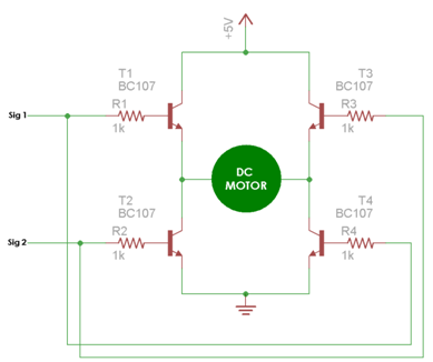
The H-bridge circuit is used to drive a DC motor in both the directions. It can also use relays to function but here we used the BJT based one. It comprises of four BC107 NPN transistors as shown in figure 2.3. The two transistor T1 and T2 are in series and those T3 and T4 are also in series. The base of all four transistors are protected y current limiting resistors R1-R4. The prevent damaging the transistors. The base signals of T1 and T4 are the same and that of T3 and T2 are also the same. The operation is simple that when Sig1 is logic 1 and Sig 2 is logic 0, it will turn ON T1 and T4 and will turn the motor in one direction same if we reverse the input logics, the motor will go in reverse direction. All four transistors are used as simple switches here.
1.5 ALGORITHM FOR THE MICROCONTROLLER CODE

The algorithm that is driving the code on the microcontroller is a multi-tasking algorithm. It has three basic functions, first is the main function to read all sensors and actuate the actuators according to the programmed threshold values. Next is the timely updating of the LCD display and the transmission of encoded string serially to the android client if the android client is present. The last task is to check the input serial buffer for commands from the android client and process them accordingly.
When the microcontroller is powered up it reads the eeprom for recovery of all programmed sensomate values and device states that whether which device was ON/OFF the last time the power failed. Then after recovery, it read all the sensor readings and process them accordingly in meaningfull values. After that the microcontroller checks the sensor readings against the programmed sensomate values and turns ON/OFF the appliances accordingly. The checking of fire occurance and LPG leak is done here in this main loop only. If there is a sign of fire or LPG leak, the microcontroller automatically switches off all the appliances and open the door to exhaust the gases and reduce emergency cricality. The sleep mode is also processed here in this loop. If the sleep mode is activated and motion is detected or someone open the door, the alarm fires and alert the user.
In the second loop, the microcontroller runs timer0 in interrupt mode and approx every 1.5 seconds it updates the LCD for sensor values and device states. The presence of the Bluetooth link is also displayed here. Also the microcontroller sends the encoded system status in a string serially to the bluetooth UART if the link is present. It is done every 0.8 second approximately. This loop is repeated infinitely as that of the main loop.
The third section programs the serial receive complete interrupt and thus whenever a serial command is received from the android client, it processes it here and actuate the command. This is again an infinite procedure and microcontroller keeps on sensing the arrival of new command.
The transmission and reception of commands to and from the android client is done wholely in ASCII code.
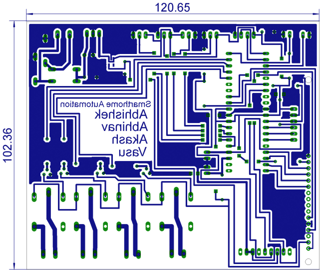
1.6 PCB FOR THE PROJECT
1.7 FEATURES OF THE PROJECT
- Control upto four home appliances wirelessly.
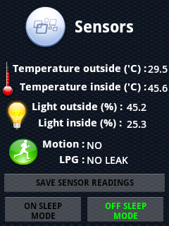
- Monitor status of your home like temperature inside and outside of your home, light intensity inside and outside of your home, motion (presence) on the main entrance, LPG leak in the home and status of you main door.
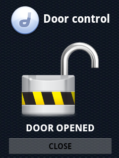
- Open/close your main door electrically and wirelessly.
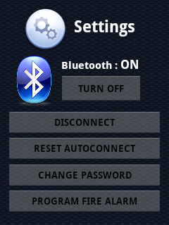
- As the android application is password protected, it automatically adds security to your home as it can be controlled by the user only.
- Automate your indoor lightening, outdoor lightening and fan/AC to switch ON/OFF automatically when the light intensity and temperature conditions exceed the programmed threshold values (This feature, is named as “SENSOMATE”).
- Has power programmable saving mode for outdoor light, such that it will automatically switch ON if a motion is detected on the main entrance, otherwise will be OFF.
- It automatically monitor your home against LPG leaks and cases of fire. If it detects something wrong,I automatically switches off all home appliances instantly and immediately opens the door to let the LPG/fire exhaust off your home.
- Has a “SLEEP MODE”, once activated will switch your light off and program the motion sensor and door sensor to raise alarm if anything goes wrong.
- As it uses Bluetooth, the user can use the android phone within a range from 10-100m (currently upto 10m because of using class 2 device).
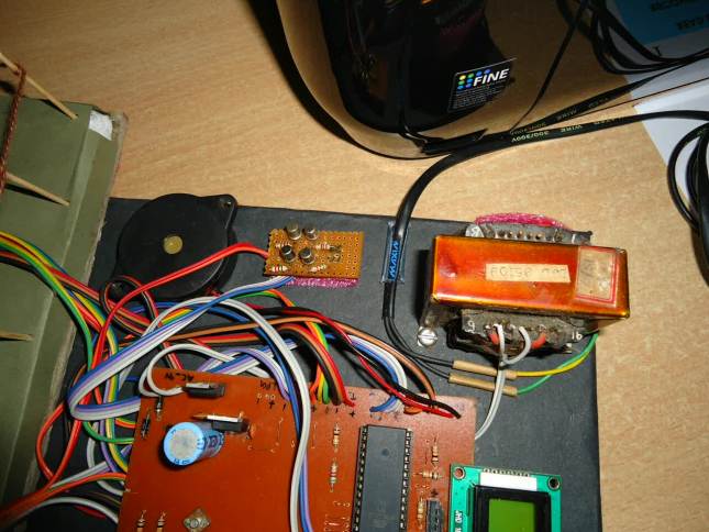
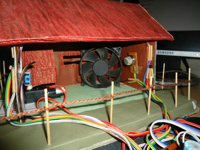
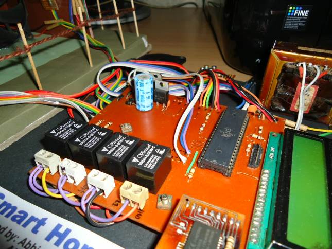
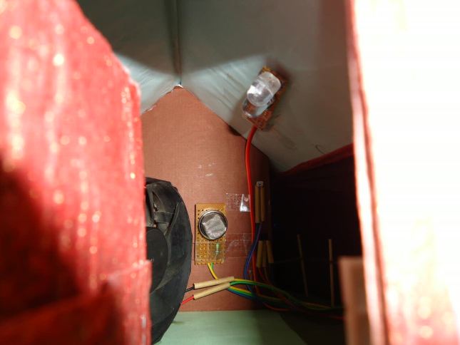
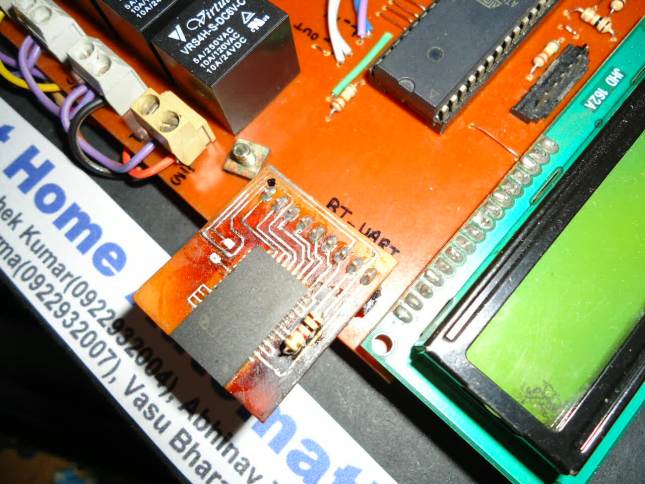
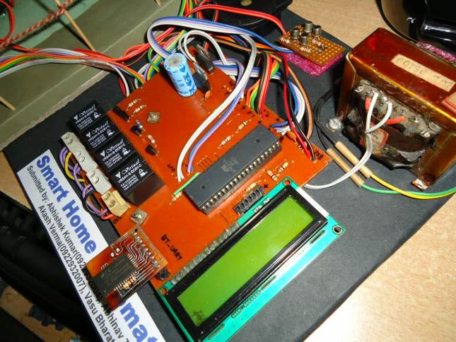
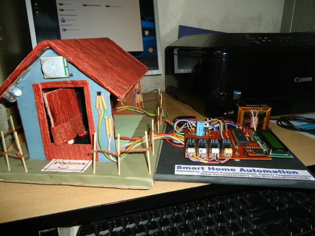
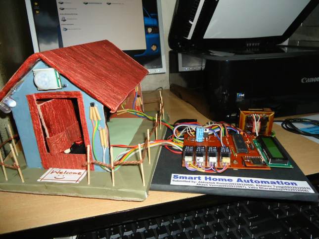
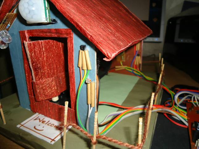
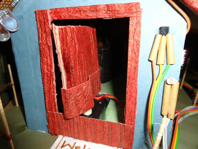
1.8 Snaps of the project


1.9 Screenshots of the android application(optimized for Samsung Galaxy Y and for 320×240 resolution phones)


Those who are interested in the project can email me at abhishekkumar1902@gmail.com for any detail.